


Home Blog Marine Battery Marine Battery Communication: Working Principles, CAN, J1939, NMEA 2000 and Modbus Explained
Marine Battery Communication: Working Principles, CAN, J1939, NMEA 2000 and Modbus Explained
Introduction
As electric and hybrid propulsion technologies continue to develop, marine electrical systems are becoming increasingly integrated. Battery performance is no longer determined by capacity and power output alone; reliable communication between the battery and other onboard equipment is also essential for safe and efficient vessel operation.
What happens when a vessel's battery cannot reliably communicate its state of charge (SOC), operating status, or fault information to the bridge display or vessel control system? Without accurate and timely battery data, crew members may have difficulty monitoring the battery's condition, while charging, power distribution, and vessel operations may be affected.
As a result, marine lithium batteries must do more than simply store and supply energy. They need to exchange data with electric propulsion controllers, battery chargers, vessel energy management systems (EMS), and onboard monitoring and display equipment. This is particularly important for LiFePO4 batteries, as their flat discharge voltage curve makes it difficult to estimate remaining capacity accurately through voltage measurements alone. A Battery Management System (BMS) must therefore monitor battery conditions, calculate SOC, and transmit operating data to connected equipment.
Understanding the fundamentals of how lithium battery communication works provides a useful starting point for understanding these interactions. Building on these fundamentals, this guide focuses on marine battery communication, explaining its working principles, communication architecture, and the roles of CAN, RS485, Modbus, SAE J1939, and NMEA 2000. It also explores key compatibility considerations to help boat builders, marine system integrators, and battery buyers select suitable communication solutions for electric and hybrid vessel projects.
1. What Is Marine Battery Communication?
A marine battery communication protocol is a set of rules that governs how a marine lithium battery exchanges data with other electronic devices on a vessel. It acts like a shared language that enables the Battery Management System (BMS), charger, Energy Management System (EMS), Power Management System (PMS), and bridge display equipment to identify and exchange information correctly.
In a vessel’s electrical system, communication is used not only to transmit battery information but also to support charging control, power coordination, status monitoring, and fault handling.
Marine battery communication generally serves three main functions:
1.1 Data Transmission
The BMS continuously collects battery operating data and sends relevant information to external devices. Common data includes:
-
Cell voltage and total battery-pack voltage.
-
Charging and discharging current.
-
Individual cell and battery-pack temperatures.
-
State of Charge (SOC), which indicates the remaining capacity.
-
State of Health (SOH), which indicates the battery’s health condition.
-
Operating status, alarms, and fault codes.
1.2 Charge and Discharge Control
Through communication, the BMS can provide the charger or vessel EMS with information such as charge permission, discharge permission, current limits, voltage limits, and protection status. External devices use this information to adjust charging and discharging parameters and keep operation within the battery’s permitted limits.
1.3 Safety Monitoring and Fault Protection
If the battery experiences overvoltage, undervoltage, overcurrent, overtemperature, abnormal temperature differences, or an insulation fault, depending on the BMS configuration, the BMS can transmit an alarm or protection status. The system may then limit power, open contactors, or stop charging or discharging according to its design.
The BMS is generally responsible for collecting battery data, evaluating battery conditions, and managing battery-level protection. The EMS and PMS coordinate energy use across the vessel. These systems work together through communication, but they perform different functions.
2. How Does Marine Battery Communication Work?
The basic principle is straightforward: the BMS collects battery data, formats it according to an agreed communication protocol, and sends it to external vessel equipment through CAN, RS485, or another communication interface. The receiving equipment decodes the data and uses it for monitoring, control, or alarms according to the system requirements. The process can be divided into five steps.
2.1 The BMS Collects Battery Data in Real Time
The BMS is the core of the battery communication system. It continuously monitors battery operation through voltage-sensing modules, current sensors, and temperature sensors.
The monitored information typically includes:
-
Cell voltage: identifies potential overcharge or undervoltage conditions.
-
Battery current: identifies whether the battery is charging or discharging and measures the current level.
-
Battery temperature: tracks temperature changes and can support power limits when necessary.
-
SOC: estimates the battery’s remaining capacity.
-
SOH: evaluates battery health and condition.
-
Insulation status: in high-voltage systems equipped with insulation monitoring, identifies potential insulation abnormalities.
Large battery systems may use a hierarchical architecture involving slave controllers, a master controller, cluster controllers, or other management levels. Different levels collect cell or module data, aggregate information, and manage the system. The actual architecture depends on the battery-system design.
2.2 The BMS Sends Data to External Devices
After collecting the data, the BMS encodes it according to the specified communication protocol and transmits it through the corresponding interface.
A typical communication path is:
Cell sensors → BMS acquisition boards → BMS master controller → CAN / RS485 / Ethernet → EMS / PMS / charger / display equipment
CAN is commonly used for real-time control and multi-device communication. It uses differential signaling and offers good noise immunity, making it suitable for vessel environments with motors, inverters, and other electrical equipment.
RS485 is also used for data exchange between batteries, monitoring equipment, industrial controllers, and communication gateways, particularly in systems using Modbus RTU.
2.3 The Vessel Management System Receives and Processes Data
After receiving data from the BMS, the EMS or PMS evaluates it in the context of battery status and vessel operating requirements. For example, the system may determine:
-
Whether charging or discharging is currently permitted.
-
How much continuous discharge power the battery can provide.
-
How power should be allocated between the propulsion system and onboard auxiliary loads.
-
Whether power should be reduced when the battery temperature becomes abnormal.
-
Whether protective action is required if communication is interrupted or a fault occurs.
The BMS primarily manages the battery itself, while the EMS and PMS coordinate the vessel’s overall electrical power system.
2.4 Two-Way Communication During Charging
Charging a marine battery involves more than supplying electrical power. The charger and BMS may need to exchange operating information so that charging can proceed safely.
A typical charging communication process includes:
-
The charging equipment establishes a communication connection with the battery system.
-
The BMS checks battery voltage, temperature, insulation status, and other safety conditions.
-
Based on the battery condition, the BMS provides charge permission and relevant charging parameters.
-
The charger follows the agreed parameters to perform charging.
-
Current, voltage, temperature, and fault information continue to be exchanged during charging.
-
If an abnormal condition occurs or a charging stop condition is reached, the system adjusts or stops charging according to its control logic.
The communication method depends on the charger, BMS, and applicable marine charging requirements. Common options include CAN and communication systems based on RS485 or Ethernet.
2.5 Battery Data Is Displayed on the Bridge or Monitoring Terminal
After passing through the communication network or a protocol gateway, BMS data can be displayed on a bridge Multi-Function Display (MFD), vessel monitoring system, or remote monitoring terminal.
Crew members may be able to view:
-
Current State of Charge (SOC).
-
Total battery voltage and operating current.
-
Battery temperature.
-
Charging and discharging status.
-
Battery alarms and fault information.
LiFePO4 batteries have a relatively flat voltage plateau over much of their discharge range. As a result, voltage alone is not sufficient to estimate remaining capacity accurately in the middle of the discharge range. The BMS generally calculates SOC using current integration, calibration, and related algorithms, then transmits the result to the display equipment.
In short, marine battery communication follows this sequence: BMS data acquisition → communication network transmission → vessel-system decoding → equipment coordination and control → alarms and protection.
3. Core Marine Battery Communication Architecture and Common Protocols
Marine battery communication involves different communication interfaces, bus technologies, and application-layer protocols. These technologies work together to enable data exchange between the Battery Management System (BMS), chargers, propulsion controllers, vessel energy management systems, and onboard display equipment.
It is important to understand that not all communication technologies serve the same function. Some define the electrical connection and signal transmission method, while others define how data is structured, transmitted, and interpreted.
3.1 CAN Bus (Controller Area Network)
CAN Bus is a common communication technology in marine battery systems. It is widely used for data exchange between the BMS, propulsion controllers, chargers, and other control devices.
Key characteristics of CAN include:
-
Multiple devices can share the same communication bus.
-
Message identifiers distinguish different types of data.
-
Priority-based arbitration manages message transmission.
-
Error detection and fault-handling mechanisms are provided.
-
It is suitable for control systems that require good real-time performance and reliability.
In vessel electrical systems, CAN can be used for battery-status transmission, charge and discharge control, and coordination between devices.
It is important to note that a CAN Bus interface does not automatically mean that a device supports J1939 or NMEA 2000. The data that can be exchanged depends on the application-layer protocol and message definitions supported by the device.
3.2 SAE J1939 Protocol
SAE J1939 is a higher-layer communication protocol based on CAN. It is widely used in engines, commercial vehicles, industrial equipment, and some marine power and propulsion systems.
It uses standardized message definitions to allow equipment from different manufacturers to exchange data according to shared rules.
Key characteristics of J1939 include:
-
It typically uses a 29-bit extended CAN identifier.
-
It organizes communication messages using PGNs (Parameter Group Numbers).
-
It defines individual parameters using SPNs (Suspect Parameter Numbers).
-
It supports broadcast communication and specific peer-to-peer communication.
Common communication rates include 250 kbps and 500 kbps, depending on the J1939 specification and system configuration being used.
In a marine lithium battery system, if the battery must connect to an engine controller, propulsion controller, or other device that supports J1939, the BMS must provide the required PGNs, SPNs, and data definitions according to the target equipment’s communication requirements.
Having a CAN interface alone does not mean that a battery supports J1939. The protocol implementation, message mapping, and communication parameters must also be confirmed.
3.3 NMEA 2000 Protocol
NMEA 2000 is a marine electronics communication standard developed by the National Marine Electronics Association. It is mainly used for data sharing among navigation equipment, instruments, engine-monitoring devices, and vessel electrical equipment.
NMEA 2000 is based on CAN and uses a standardized network and parameter-group structure, allowing compliant devices to connect to the same marine network.
In marine battery systems, NMEA 2000 can be used to transmit battery operating data to vessel MFDs or monitoring equipment.
Common data may include:
-
Battery State of Charge.
-
Battery voltage and current.
-
Battery temperature.
-
Battery status and alarm information.
If the BMS natively supports NMEA 2000, it can communicate according to the applicable standard. If the BMS uses another communication protocol, a compatible protocol gateway may be required to convert the data.
A CAN interface by itself does not establish NMEA 2000 compatibility. The device must also meet the relevant protocol implementation, data-mapping, and network requirements.
3.4 RS232, RS485 and Modbus
RS232 and RS485 are serial communication interface standards, while Modbus is an application-layer communication protocol. They are often used together, but they serve different purposes.
Common communication configurations include:
-
RS485 + Modbus RTU.
-
Ethernet + Modbus TCP.
-
RS232 + a device-specific serial communication protocol.
RS232 is generally used for point-to-point communication over relatively short distances. It is commonly found in configuration interfaces, service ports, and connections between individual devices.
RS485 supports differential signal transmission and is suitable for longer communication distances and multi-device networks. It is commonly used for data exchange between battery management systems, monitoring equipment, industrial controllers, and communication gateways
Modbus RTU is a serial communication protocol commonly used over RS485. It typically uses a master-device polling mechanism to read information such as battery voltage, current, SOC, temperature, and fault codes.
The actual communication speed, register addresses, data formats, and device configurations must be confirmed before integration.
3.5 Ethernet and Modbus TCP
Ethernet is used in more complex vessel electrical systems where multiple devices need to exchange data through a network.
Modbus TCP is an application-layer protocol that operates over TCP/IP networks, commonly using Ethernet as its physical network infrastructure.
In marine battery systems, it can be used to connect battery monitoring equipment with vessel energy management systems (EMS), supervisory computers, and remote monitoring platforms.
Typical applications include:
-
Centralized monitoring of multiple battery systems.
-
Data exchange between battery monitoring equipment and EMS platforms.
-
Integration with PLCs and supervisory control systems.
-
Remote monitoring and system-level data management.
Compared with simple serial communication, Ethernet-based networks offer more flexible network expansion and integration. However, network topology, IP configuration, device compatibility, and cybersecurity requirements should be considered during system design.
3.6 Other Communication Technologies
In addition to the main communication technologies described above, some marine battery systems may use other communication methods depending on the application.
CAN open
CANopen is a higher-layer communication protocol based on CAN. It defines device objects, process data, parameter configuration, and network management mechanisms. It can be used with specific industrial control devices and battery systems.
NMEA 0183
NMEA 0183 is an earlier serial communication standard for marine electronic equipment. It is commonly used by GPS, AIS, compasses, and other navigation devices. It is different from NMEA 2000, and the two standards should not be treated as directly interchangeable.
IEC 61850
IEC 61850 is a communication standard for power automation systems. It may be used in large vessel power stations, complex electrical distribution systems, and advanced energy management applications. It is not a typical communication interface for an ordinary marine battery BMS.
Bluetooth
Bluetooth is mainly used for short-range battery monitoring, mobile app access, parameter viewing, and after-sales troubleshooting. It provides convenient local access to battery information but cannot replace the wired communication networks required for vessel control and system integration.
4. Why Does a Marine Battery Need Data Communication?
Marine battery communication is essential for more than displaying the remaining battery capacity. It enables connected vessel equipment to monitor battery conditions, coordinate power usage, and respond to abnormal operating conditions.
4.1 More Accurate State-of-Charge Monitoring
LiFePO4 batteries have a relatively flat discharge-voltage curve across much of their operating range. This means that battery voltage alone cannot reliably indicate the remaining capacity.
A Battery Management System (BMS) estimates the State of Charge (SOC) using current measurement, voltage monitoring, temperature information, and battery-capacity calculation algorithms.
Through a compatible communication interface, the BMS transmits SOC and other operating information to bridge displays, vessel monitoring systems, and energy management equipment.
This allows crew members to monitor the battery's remaining capacity and operating condition more accurately.
4.2 Improved Battery Safety and Fault Monitoring
Marine battery systems may contain multiple battery modules connected in series or parallel. Continuous monitoring is therefore important for maintaining safe and stable operation.
The BMS monitors key parameters such as cell voltage, battery current, temperature, and protection status. Relevant information can be transmitted to the vessel management system through the configured communication network.
When an abnormal condition occurs, such as overvoltage, undervoltage, overcurrent, or overtemperature, the BMS can generate alarms and activate protection functions according to its design.
The vessel monitoring system can then display the relevant information, helping crew members identify potential problems and respond appropriately.
4.3 Coordination Between Propulsion and Vessel Energy Systems
On electric and hybrid vessels, the battery may supply energy to propulsion motors as well as onboard auxiliary equipment.
Communication between the BMS, Energy Management System (EMS), Power Management System (PMS), and propulsion controller helps coordinate the use of available electrical power.
For example:
-
The propulsion controller can receive information about the battery's permitted discharge power.
-
The EMS can coordinate energy distribution according to battery status and vessel operating requirements.
-
The PMS can monitor the overall electrical power system.
-
Connected equipment can respond to battery alarms or power limitations according to the configured control strategy.
This coordination is particularly important for vessels that operate for extended periods, require frequent charging and discharging, or depend on a stable electrical power supply.
5. Marine battery communication Tecaahnologies Compared
When selecting a communication solution for a marine lithium battery, it is important to understand the differences between communication interfaces, bus technologies, and application-layer protocols.
A communication interface mainly defines the electrical connection and signal transmission method. A bus technology provides the communication mechanism between connected devices, while an application-layer protocol defines how data is organized and interpreted.
For example, RS485 is an electrical interface standard, while Modbus RTU is an application-layer protocol commonly used over RS485. Similarly, CAN is a communication bus technology, while SAE J1939 and NMEA 2000 are higher-layer communication standards based on CAN.
Therefore, having the same communication interface does not automatically mean that two devices can exchange data correctly.
5.1 Comparison of Common Marine Battery Communication Technologies
|
Technology
|
Type / Communication Basis
|
Typical Applications
|
Key Characteristics
|
|
CAN Bus
|
Communication bus technology
|
BMS, propulsion controllers, chargers
|
Multi-node communication, message arbitration, error detection
|
|
RS232
|
Serial electrical interface
|
Configuration ports, individual device connections
|
Point-to-point communication
|
|
RS485
|
Differential serial electrical interface
|
BMS, monitoring equipment, controllers
|
Good noise immunity, multi-point connections
|
|
Modbus RTU
|
Serial application-layer protocol
|
Battery monitoring, industrial controllers
|
Register-based data exchange, master polling
|
|
Modbus TCP
|
Application-layer protocol over TCP/IP
|
EMS, supervisory computers, monitoring platforms
|
Ethernet-based network integration
|
|
SAE J1939
|
Higher-layer protocol based on CAN
|
Engines, propulsion systems, power equipment
|
Uses PGN and SPN data definitions
|
|
NMEA 2000
|
Marine communication network standard based on CAN
|
Marine displays, instruments, engine and battery monitoring
|
Standardized marine network communication
|
|
CANopen
|
Higher-layer protocol based on CAN
|
Industrial control equipment
|
Standardized device objects and network management
|
|
NMEA 0183
|
Serial marine communication standard
|
GPS, AIS, navigation equipment
|
Commonly used in traditional marine electronics
|
|
Bluetooth
|
Short-range wireless communication
|
Mobile apps, local battery monitoring
|
Convenient wireless access to battery information
|
The actual communication capabilities depend on the BMS hardware, firmware, protocol implementation, and the specifications of connected equipment.
5.2 What Is the Difference Between CAN and RS485?
CAN and RS485 are both used in battery communication systems, but they operate differently and should not be considered direct equivalents.
CAN Bus provides a communication mechanism in which multiple devices can share the same bus. Messages are identified by their identifiers, and bus arbitration determines which message is transmitted first. CAN also includes error detection and fault-handling mechanisms, making it suitable for systems that require reliable communication and coordinated control.
RS485 mainly defines the electrical signal transmission method. It supports differential signaling and is commonly used for longer-distance serial communication and multi-device connections. However, RS485 does not define the actual data structure or application-level communication rules. It normally requires an additional protocol, such as Modbus RTU.
In practical marine battery applications:
-
CAN is commonly used for communication between the BMS, propulsion controllers, and charging equipment.
-
RS485 is frequently used for battery monitoring, industrial controllers, and communication gateways.
-
The choice depends on the target equipment, system architecture, and required communication functions.
5.3 What Is the Difference Between J1939 and NMEA 2000?
SAE J1939 and NMEA 2000 are both based on CAN technology, but they are designed for different application environments and use different communication definitions.
SAE J1939 is widely used in engines, commercial vehicles, industrial equipment, and marine power or propulsion systems. It organizes communication messages using PGNs and defines individual parameters through SPNs.
NMEA 2000 is designed specifically for marine electronic networks. It enables navigation equipment, instruments, sensors, engine systems, and compatible electrical devices to exchange standardized data.
In marine lithium battery applications:
-
If the battery needs to communicate with a J1939-compatible engine or propulsion controller, the BMS must support the required J1939 messages and data definitions.
-
If battery information needs to appear on an NMEA 2000 marine display or multifunction display (MFD), the BMS must support the required NMEA 2000 data or use a compatible protocol gateway.
-
If a vessel uses both networks, the communication architecture and data conversion requirements must be evaluated separately.
Although both technologies use CAN, their message definitions, network requirements, and device compatibility are different.
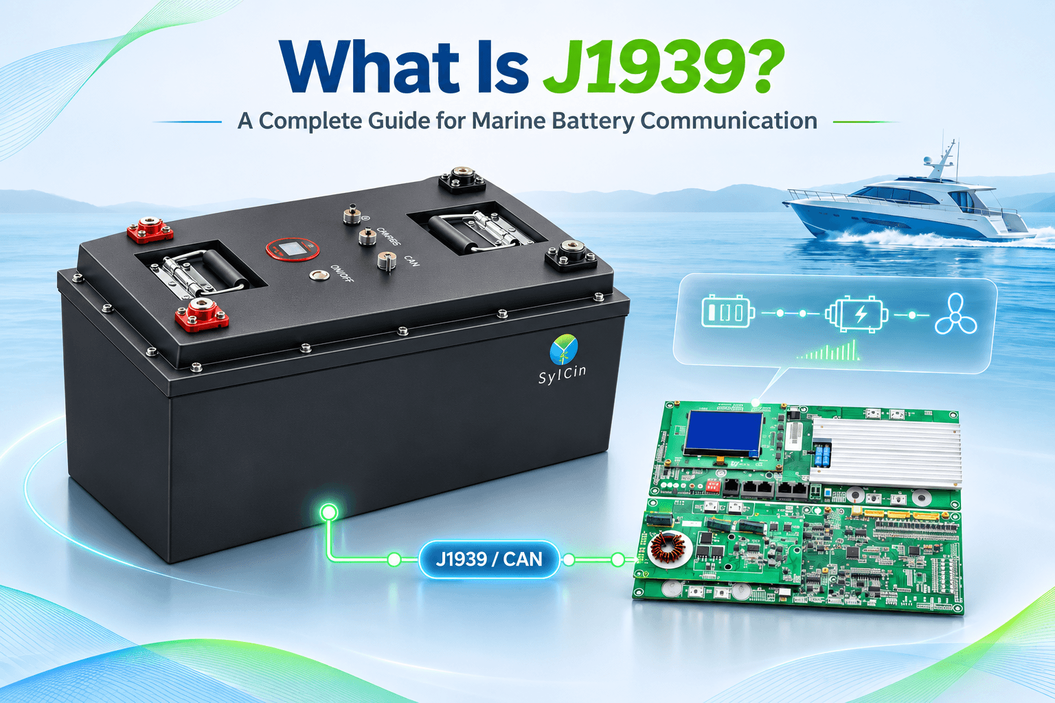
For more detailed technical explanations, see our dedicated guides: What Is J1939? and What Is NMEA 2000?
5.4 What Is the Difference Between Classical CAN and CAN FD?
Classical CAN and CAN FD are two versions of CAN communication technology.
A Classical CAN data frame carries up to 8 bytes of data, while CAN FD supports up to 64 bytes of data in a single frame.
CAN FD can improve data-transfer efficiency by carrying more information per frame. However, all devices on the network must support the appropriate CAN FD hardware and communication configuration.
A Classical CAN device should not automatically be assumed to support CAN FD. Compatibility must be checked before connecting devices that use different CAN versions.
6. Marine Battery Charing Communication Requriements
Depending on the system design, the following information may be exchanged between the BMS and charging equipment:
|
Data Item
|
Purpose
|
|
Battery Voltage
|
Monitors the current battery-pack voltage
|
|
Charging Current
|
Monitors the current charging level
|
|
Maximum Charging Current
|
Defines the permitted charging-current limit
|
|
Maximum Charging Voltage
|
Defines the permitted charging-voltage limit
|
|
Charge Permission
|
Indicates whether charging is allowed
|
|
Battery Temperature
|
Monitors battery thermal conditions
|
The actual data points and control functions depend on the BMS and charger specifications.
6.2 Common Communication Problems During Charging
Even when a marine battery and charger have communication interfaces, they may not communicate correctly if their protocols or configurations are incompatible.
Common problems include:
-
Protocol mismatch: The BMS and charger use different communication protocols or message definitions.
-
Incorrect communication speed: The CAN baud rate or serial communication parameters do not match.
-
Incorrect data mapping: The charger cannot correctly interpret the battery's voltage, current, or charging-limit information.
-
Charging permission errors: The charger does not correctly recognize the BMS charge permission or protection status.
-
Communication interruptions: Wiring problems, connector faults, electrical interference, or network configuration issues interrupt data transmission.
6.3 How to Improve Charging-System Compatibility
Before integrating a marine battery with a charger, both manufacturers' communication specifications should be reviewed.
Important information to confirm includes:
-
Supported communication interface and protocol.
-
CAN baud rate or serial communication parameters.
-
Message IDs, PGNs, or Modbus register addresses.
-
Battery voltage and charging-current limits.
-
Charge permission and protection signals.
-
Data update intervals and fault-handling logic.
The battery and charger should then undergo communication and charging tests using the actual equipment.
For customized marine lithium battery projects, confirming these requirements during the design stage helps reduce integration problems during installation and commissioning.
7. How to Choose the Right Communication Protocol for a Marine Lithium Battery
When selecting a marine battery communication solution, do not look only at whether the battery has a CAN or RS485 interface. The decision should be based on the vessel’s system architecture, target equipment, and actual application requirements.
The following factors should be considered.
7.1 Identify the Vessel Application
Different vessel types may have different battery communication requirements.
| Vessel Application | Typical Communication Requirements |
| Inland fishing boats | Battery status monitoring, SOC display, and charging management |
| Recreational yachts | Integration between the battery, marine display equipment, and navigation network |
| Workboats | Battery monitoring, propulsion-system communication, and fault alarms |
| Electric vessels | Communication among the BMS, propulsion controller, charger, and EMS |
| Hybrid vessels | Coordination among the battery, engine, generator, and energy management system |
| Small passenger ferries | Battery status monitoring, propulsion power coordination, and safety protection |
7.2 Confirm the Communication Protocols Supported by Target Equipment
Before customizing a battery, identify the communication protocols used by the equipment already installed on the vessel. For example:
-
Does the propulsion controller support SAE J1939?
-
Does the marine display support NMEA 2000?
-
Does the charger use CAN or Modbus?
-
Does the vessel EMS support Modbus TCP?
-
Is a gateway required to connect different communication networks?
These details determine which communication method the battery BMS should use and whether an additional protocol-conversion device is required.
7.3 Confirm the Specific Communication Parameters
In addition to the interface and protocol name, the detailed communication parameters must also be confirmed.
| Customization Item | Details to Confirm |
| Communication interface | CAN, RS485, RS232, Ethernet |
| Communication protocol | J1939, NMEA 2000, Modbus RTU/TCP, etc. |
| Communication speed | 250 kbps, 500 kbps, or the project-specified rate |
| Data definitions | PGN, SPN, register addresses, and data formats |
| Data content | SOC, SOH, voltage, current, temperature, and alarms |
| Data update cycle | Transmission frequency for different data points |
| Control functions | Charge permission, discharge limits, and fault protection |
| Connections | Connectors, wiring harnesses, gateways, and termination matching |
For a J1939 project, confirm the PGNs, SPNs, 29-bit identifiers, data scaling, and update intervals required by the target equipment.
For an NMEA 2000 project, confirm the relevant PGNs, data mapping, device compatibility, and network requirements.
7.4 Consider the Actual Operating Environment
Marine batteries operate in environments that may involve high humidity, salt spray, vibration, and vessel movement. Therefore, communication design must consider not only data transmission but also the reliability of connectors and wiring.
Key factors include:
-
Vibration: Continuous vibration may loosen connectors or fatigue wiring. Reliable fixing and connection design are important.
-
Corrosion: Sea-water salt spray can corrode metal terminals and connectors. Corrosion-resistant materials and sealing should be considered.
-
Water protection: Select an appropriate ingress-protection rating according to the installation location and actual operating environment.
-
Vessel movement: Battery installation and wiring must be secured to withstand vessel tilting, rolling, and movement during navigation.
-
Electromagnetic interference: Propulsion motors, inverters, and other high-power equipment may generate interference. Communication routing, shielding, and grounding should be planned accordingly.
7.5 Perform Communication Compatibility Testing in Advance
Before mass production or project delivery, the battery BMS should be tested with the target equipment under the actual communication configuration.
Key checks include:
-
Can the BMS transmit battery data correctly?
-
Can the external equipment decode the data accurately?
-
Are SOC, voltage, current, and temperature readings consistent?
-
Can the charger read the required charging parameters correctly?
-
Do fault alarms and protection commands work as intended?
-
Does the system respond to communication loss according to its protection design?
Only after communication between the actual devices has been verified can the system’s integration requirements be considered validated for the project.
8. FAQ: Frequently Asked Questions About Marine Battery Communication
8.1 Why Do Marine Lithium Batteries Need Communication?
Marine lithium batteries communicate with chargers, vessel management systems, and display equipment to provide SOC, voltage, current, temperature, and fault information. This helps crew members understand battery operation and supports charge and discharge control, energy management, and fault alarms.
8.2 What Are the Most Common Communication Protocols for Marine Batteries?
Common communication technologies include CAN, RS485, Modbus, SAE J1939, and NMEA 2000. The appropriate method depends on the requirements of the battery BMS, propulsion controller, charger, and marine display system.
8.3 Does a CAN Interface Mean the Battery Supports J1939?
No. CAN is an underlying communication technology, while J1939 is a higher-layer protocol based on CAN. Even if a battery has a CAN interface, its support for J1939 message definitions, PGNs, SPNs, and communication parameters must be confirmed separately.
8.4 Can NMEA 2000 Connect to a Marine Lithium Battery?
Yes, provided that the battery BMS natively supports NMEA 2000 or a compatible protocol gateway converts the battery data into information recognized by the NMEA 2000 network. Data mapping and device compatibility must also be confirmed.
8.5 What Is the Difference Between RS485 and Modbus?
RS485 is an electrical interface standard that mainly defines the signal-transmission method. Modbus is an application-layer communication protocol that defines how devices exchange data. They are commonly used together, for example, RS485 + Modbus RTU.
8.6 Can a Marine Battery Support Both J1939 and NMEA 2000?
This can be designed according to project requirements, but the BMS communication interfaces, protocol implementations, data mapping, and network architecture must be confirmed. Some systems may require separate communication interfaces or a protocol gateway. A single CAN interface does not automatically provide compatibility with both protocols.
8.7 Can Marine Battery Communication Be Customized?
Communication interfaces, protocols, data definitions, communication speeds, wiring harnesses, and connectors can be evaluated according to project requirements. The functions that can be implemented must be confirmed against the BMS hardware, software, and target equipment specifications.
8.8 Why Can a Marine Display Fail to Read a Battery Even When the Battery Has a CAN Interface?
Possible causes include a protocol mismatch, incorrect baud rate, incorrect PGN or data mapping, device-address configuration issues, or wiring, termination-resistor, and network-configuration problems. Review the BMS and display communication documents and perform actual message testing.
8.9 Can Bluetooth Replace CAN or NMEA 2000 for Marine Batteries?
Generally, no. Bluetooth is mainly used for short-range battery monitoring and after-sales maintenance. CAN and NMEA 2000 provide wired data exchange and system integration between vessel devices. Bluetooth should not replace the main communication network required by vessel control systems.
8.10 What Communication Information Should Be Provided When Ordering a Custom Marine Lithium Battery?
Provide the model of the target controller or display, the communication protocol, interface type, communication speed, PGN/SPN or register definitions, and the list of data points and control functions required. More complete information helps the engineering team evaluate communication compatibility.
Conclusion
Marine battery communication is an important part of the electrical power system on electric and hybrid vessels. Through technologies such as BMS, CAN, RS485, Modbus, SAE J1939, and NMEA 2000, marine lithium batteries can exchange data with chargers, propulsion controllers, vessel energy management systems, and bridge display equipment. This supports battery-status monitoring, charge and discharge coordination, and fault protection. Different communication protocols have different technical characteristics and application areas.
Selection should therefore consider more than whether the interfaces match: message formats, data definitions, communication parameters, and actual compatibility with target equipment must also be confirmed. For a customized marine lithium battery project, define the voltage, capacity, application, and communication requirements early, then verify system integration through testing with the actual equipment.
SylCin provides OEM/ODM marine lithium battery solutions and can evaluate battery specifications, BMS configurations, communication protocols, and system integration requirements according to each project. If you are planning a marine battery project or need a customized communication solution, Contact Our Team to discuss your requirements with our engineering team.
Release time: 2026-11-05
What Is J1939? A Complete Guide for Marine Battery Communication
Best Selling Product





Would you like to talk to us about your battery project?

+0086 075527616594

sylcin02@sylcin.com

Room 1701, Building A, Zhongan Science and Technology Park, Dalang Street, Longhua District, Shenzhen